Text, Install and Photos by Toby Mosholder
So
you got that new 4-link installed,
you’ve scrapped up the extra
change for the big bad boy bags and
air management system. Countless
nights getting everything installed
and the first time you hit the switch
you notice your rear end shift about
half a foot…WTF?? You were
expecting it to hop. Your heart starts
to race, you get enough courage to
hit the switch and lower the truck
back down to the ground. The rear
end went right back into place.
There is no need to go kill the
installer. This is very common with
4 link suspensions. The perfect cure
for this problem is the Watts Link
from KP Components. www.kpcomponents.com
So,
this month’s article is
how to install the new KP Components
Watts Link on an 88-98 Full-size
Chevy pickup. To start; I sent this
kit off to get nickel plated so it
would match my 4 links bars. We removed
the bed next; I believe it is not
necessary to do this in all cases.
It can be done easily on most trucks
with the bed on. I installed an 8
piece c-notch at the same time: this
is why the bed is off the truck.
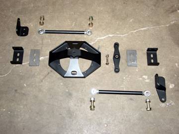
Step 1: The first step is
to lay all the parts out and check
against the hardware list to make
sure all pieces were accounted for.
Step 2.
Start assembling the links with
the heims joints and jam nuts.
It would be helpful to use anti-seize
compound on ALL threads in this
installation. Install the jam nut
on to the heims joint then thread
the heims joint into the link bar.
Twist the Heim’s joints
into the link bars till there are
only 4 threads showing on the Heim’s
joint. Do this to both link bars.
Step 3.
Install the center link into the
center section. Insert the two
urethane bushings into the center
link. Now using the ½”x3” bolt,
2- ½” flat washers
and one ½” steel lock
nut bolt the center link to the center
section with the nut closest to the
differential cover and tighten.
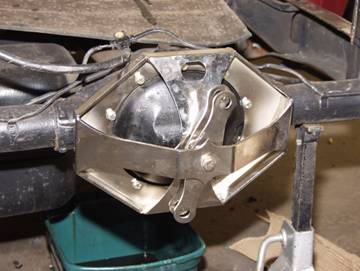
Step 4. Install the
center section to the rear end. Hold
constant pressure against the differential
cover to minimize fluid loss.**You
may want to ask for an extra hand
with this step** Discard the original
bolts and then place the center section
to the differential cover. Make sure
that the brake line relocation hole
is facing up and to the drivers side.
Now install the 10 – 5/16
x 1 ½” bolts with a
locking washer and flat washer on
each bolt supplied in the kit.
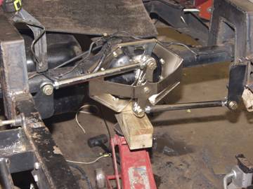
Step 5. Install
one end of each link bar to the
center link using two ¾”x 2 ½”,
four ¾” flat washers
and two ¾” lock nuts.
Then bolt the frame brackets to the
other end of the link bars using
the ¾”x 2 ½” bolts,
two ¾” flat washers,
and two ¾” steel locking
nuts.
Step 6. Now you will turn
your attention the brackets that
attach to the frame. Depending on
your personal frame set up. There
are several ways to attach the brackets
to the frame. We will use the 8-
piece step notch installation on
this one.
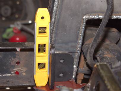
First position the rear end on the
stands to proper ride height. (This
is height the vehicle will be at
during normal driving)
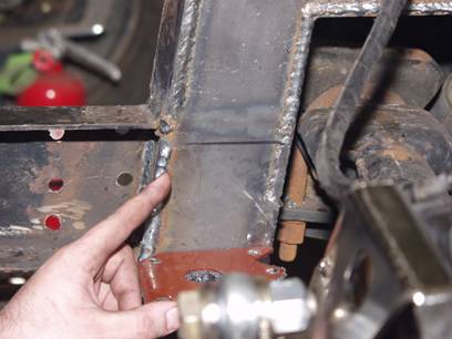
Now
transfer a mark onto the inside
plates of the step notch ½” below
the top edge of the frame rail. Place
the driver’s side bracket up
against the frame using the marks
to line up the bracket:

Move
the bracket back and forth until
the link bar is parallel with the
rear end and clamp into position.
Now mark the two holes and drill
1/2” holes. Bolt the driver’s
side bracket into place using two ½” x
1 ¼” bolts, ½” flat
washers and ½” lock
nuts. (I chose to weld mine in) Now
repeat this process on the passenger
side.
Remove
the bracket that held the brake
line tee to the differential and
attach it to the watts link bracket
using one 5/16” x 1 ¼” bolt,
5/16” flat washers, and 5/16” locking
nut.
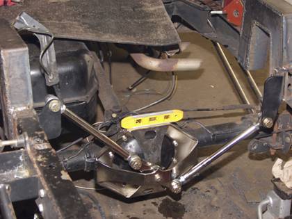
Step 7. To align the rear
end in the frame rails you will measure
from the step notch to the backing
plate on the rear end. Compare these
measurements from both sides and
determine how far the rear end will
need to be moved. Once that distance
is found have a friend measure from
the step notch to the backing plate
like before, and slowly turn BOTH
link bars until the same distance
is achieved on each side. Tighten
all four jam nuts. Now cycle the
suspension and make sure there is
no binding any where.
|