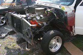
Step
One: (below)
You will need to pull the motor to install the Dropmember. In our case we stripped
the Truck down to the frame in preparation for more modifications. |
 |
|
Step
Two: (not pictured)
You will need to dismantle all the original steering components.
You will not be using any of this back.
|
| |
|
 |
|
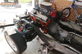
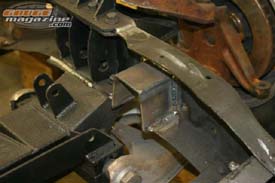
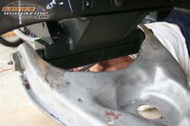
Step Three: (above)
Start to remove the original suspension and cross member. This can be done as
one piece. We decide dto take the suspension apart then drop the cross member
down. Be prepared, these bolts and nuts have been installed for 25+ years. |
|
 |
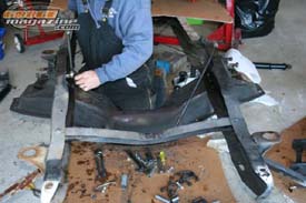
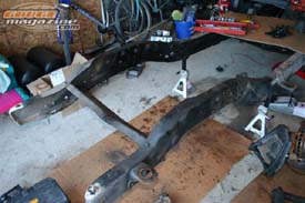
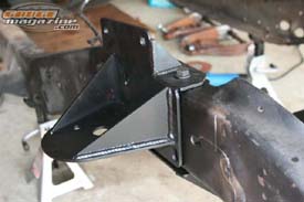
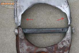
Step
Four: (above and below)
You will need to install a notch in front of the Dropmember. This will give the
Mustang II adequate clearance. You can cut this out using what ever you want.
The provided notch will need to be welded into to place. It is located 4.25” from
the front lower mounting hole of the dropmember. |
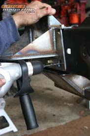 |
Step
Five: (right)
Next you will have to get out your ½” drill. You will need to
open up several of the factory holes. At this point we also went ahead and
sprayed all the bare metal pieces in an Etching Primer. |
 |
|
Step Six: (left)
After drilling out the original holes you can install the inner frame
piece.
|
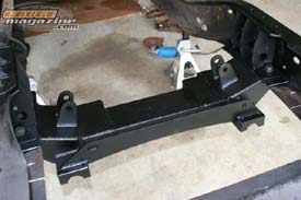
Step Seven: (right)
Next we installed
the main section of the Dropmember. There are three ½” Grade
8 bolts that go in each side. It will take a little tweaking to get
all the holes to line up. We used a pry bar to spread the frame rails
the small amount we needed to get it to line up perfectly. |
|
| |
|
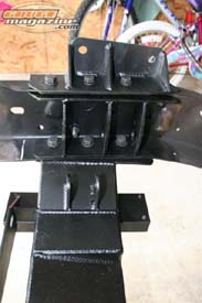 |
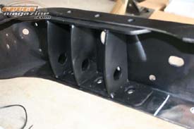
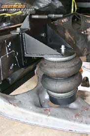
Step
Eight: (left, below)
Now you can install the bag mount/upper control arm mount. You will
have to drill one extra hole on each side. There are seven 7/16” Grade
8 bolts per side you will have to install and tighten on this piece alone.
|
|
|
|
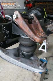
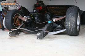
Step Nine: (above, upper left, left)
Now you can install
the lower control arms. The kit comes with a locator pin that needs to
go into the cross-shaft and bottom of the mount. Then you sandwich the
cross-shaft with the other mounting piece and use the ten 5/16” Allen
head bolts. If you are using your stock lower control arms, you will
have to trim a small amount off. If you are installing the Strong Arms
you will have to drill new air bag mounting holes. |
|
| |
|
|
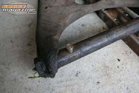
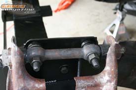
Step Nine - A (left)
In the picture you can see the small amount trimmed off of the lower
control arm. We test fitted it several times so that we trimmed as little
as possible. |
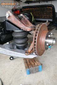
Step Ten: (right)
Next we installed the airbag. The top of the bag installs to the Dropmember.
A spring cup is mounted to the bottom of the bag. If you install the Strong
Arms the bag will mount to the control arm. |
 |
|
Step Eleven: (left)
Next we installed the upper control arms using the supplied hardware. |
Step
Twelve: (right)
Before installing the spindle, it will need a slight modification. The
steering arm will need to be drilled out the 5/8”. This allows the
mounting the heavy duty Heim joint used on the Mustang II Rack . Once that
is done you can install the spindle. After drilling out the steering arm
install the drop spindle.
Step Thirteen: (not pictured)
With all this installed you can install the Mustang II Rack. The kit comes
with aluminum bushings that you use to install the Dropmember. The kit includes
and extension and a Heim for each side. This mounts to the rack and to the
spindle.
|
 |
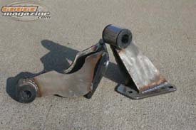
Step
Fourteen: (right)
The kit also comes with new motor mounts. Our kit came with mounts for
a Small Block Chevy. |
 |
Final Note:
Once you get to this point you will need to install a new power steering
pump or a pressure reducer. You will also have to get a few steering joints
and a shaft. This kit also comes with a new transmission cross-member.
The cab will have to be slightly modified as well, you will have to install
a larger transmission hump.
Special Thanks:
Porterbuilt Street Rods
www.porterbuiltstreetrods.com
(480) 326-6303
Unisteer
www.unisteer.com
1-800-338-9080
The Draggin Lair
(615) 512-8301
|